Pay close attention to the following steps for a trouble free installation experience.
Step 7: Ref. Fig. 5: Place the seals over the flange lip which is located on existing plumbing. DO NOT PLACE SEALS ON VALVE ***VERY IMPORTANT STEP***
If you put the seals on the valve instead of the flange, it will leak immediately after installing.
Step 8: Ref. Fig 6. and Fig. 7: With gate closed apply a thin even coat of supplied lubricant (Molykote 111) to entire surfaces on both sides of gate. DO NOT OVERLUBE. The packet is good for a repeat application – save in a sealed plastic bag.


Step 9: Ref Fig. 8: Separate pipe flanges and insert Drain Master with gate closed making sure the seals are in their correct position on the flanges. See Step 7. Rotate the valve to align the four bolt holes with the flange holes and insert the four new bolts and nuts.


Step 10: Ref. Fig. 9: Install four bolts and nuts and hand tighten till the valve is seated snug with no gap between the body and the flanges. Use 7/16″ Sockets/spanners – a Torque wrench is highly recommended. Torque from nuts side only, ¼ turn at a time, in a crisscross pattern. Progressively increase Torque to 10 inch lbs.
Max. permissible is 15 inch lbs if required to prevent leaks (Step 11). Do not exceed – components are plastic and may stress and/or crack.
If you’re valves won’t open or close, this is due to overtightening 99% of the time.
As a generic guideline 1 turn beyond finger tight equates to approx. 10 inch. lbs and 1 ½ turns aprox. 15 inch lbs – tightening beyond that risks stressing and/or cracking.
Click the button below for a pdf/manual of the full instructions.
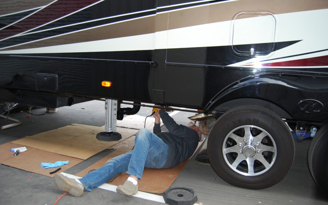
Ray at LoveYourRV.com walks you through his process of installing the Drain Master Electric RV Waste Tank Valves on his blog.